Serving as
the mainstream high-speed transport technology, 40/100G is the choice of
data centers to solve the bandwidth bottlenecks facing high traffic
service. Thus CFP transceiver is introduced at the point to meet those
requirements. This article offers a simple CFP wiki, addressing
rudiments of CFP /CFP2/CFP4 transceiver module. Let�s see how data
centers could benefit from adopting CFP transceiver.
CFP Wiki: The Choice of Data Center
The
CFP MSA (Multi-Source Agreement) defines hot-pluggable optical
transceiver form factors to enable 40/100G and the looming 400G
applications. It includes pluggable CFP, CFP2 and CFP4 transceivers to
support the high bandwidth requirements of data communication networks.
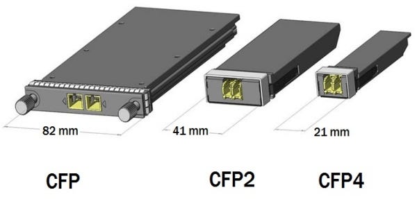
Compared with CFP form factor, the latter CFP2 and CFP4 module are of
smaller size, and will double and quadruple front panel port density,
respectively. CFP 2 and CFP4 modules support existing and future duplex
single-mode fiber (SMF) and multimode fiber (MMF) interfaces. The figure
below shows drawings of the CFP, CFP2, and CFP4 form factors. Let�s go
further to have a detailed understanding of each.
CFP Transceiver Module
CFP
(C=100 in Roman numerals; Centum) refers to 100G form-factor pluggable,
which is a new ultra high speed pluggable I/O interface supporting 40
and 100G Ethernet applications. CFP transceiver is defined by MSA
(Multi-Source Agreement) for high-speed digital signal transmission,
like carrier networks, data centers and wireless equipment. The original
CFP specification was proposed at a time when 10 G signals were far
more achievable than 25 G signals. As such to achieve 100 Gbit/s line
rate, the most affordable solution was based on 10 lanes of 10 Gbit/s.
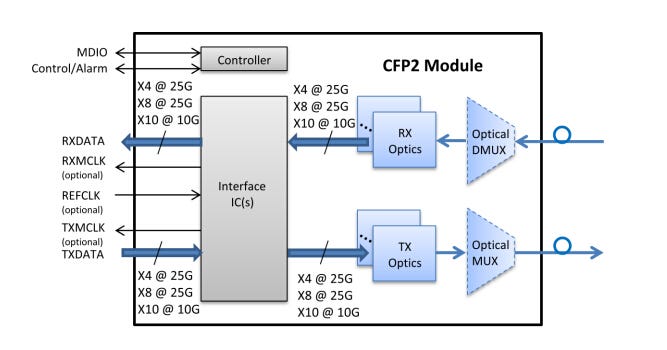
CFP2 Transceiver Module
Advances
in technology have brought about CFP2 MSA. CFP2 module specifies a
form-factor of 1/2 in size of the CFP module. The CFP2 module electrical
interface varies by application, but the nominal signaling lane rate is
25Gbit/s per lane. Its interface can also optionally support a nominal
signaling lane rate of 10Gbit/s. CFP2 module may be used to support
single-mode fiber (SMF) and multimode fiber (MMF). Designed for optical
networking, the size of CFP2 module has been chosen to accommodate a
wide range of power dissipations and applications. The module electrical
interface has been generically specified to allow for supplier-specific
customization around various 4 x 25Gbit/s interfaces, but can support
8x25Gbit/s, 10x10Gbit/s, and 8x50Gbit/s.
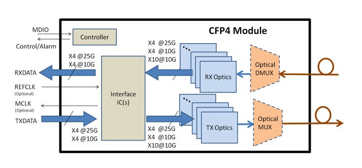
CFP4 Transceiver Module
Then
here comes the latest CFP4 hot-pluggable transceiver module. CFP MSA
defined the CFP4 form factor as an optical transceiver to support
40/100G interface for Ethernet, Telecommunication and other
applications. Identical to CFP2 module, the electrical interface of CFP4
will vary by application, the nominal signaling lane rate is also
25Gbit/s. The CFP4 electrical interface can also optionally support a
nominal signaling lane rate of 10Gbit/s. With 1/4 the size of CFP
module, CFP4 can be used to support SMF and MMF optics. CFP4 electrical
interface is specified to allow for customization specified by supplier
with various 4 x 25Gbit/s and 4 x 10Gbit/s interfaces.
Summary
CFP,
CFP2 and CFP4 are 100G hot-pluggable form factors designed for
optical communication applications compliant with 40/100G IEEE 802.3
standard, which is a great fit for 40 and 100G Ethernet data center
applications. CFP2 and CFP4, with smaller size and 2.8 times faster
speed than current CFP module, enables higher network density and more
design flexibility. This article only provides CFP wiki and some basic
information of CFP, CFP2 and CFP4.